December 10, 2011

Intercooler Plumbing Preview

These have been welded up for a few weeks now. I've been busy with school finals and haven't had a chance to throw them up here.


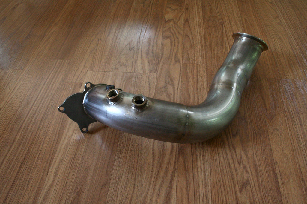
Most of the tubing and the blowoff valve flange came from Treadstone while the unpolished piece came from Vibrant (a tighter radius bend to fit between the throttle and the brake reservoir). Welded to that unpolished piece are two Earl's 1/8" NPT bungs for my IAT sensors. It turned out that these bungs were too tall for the sensors, so I actually machined them, then I drilled out the first 1/4" of the threads so I could tap deeper into the piece. The piece on the upper left is the intake. I mocked this up using an old 5" AEM filter (from an old AEM CAI). The filter will reside nicely where the windshield washer reservoir used to be. I fabbed up a nice bracket, that utilizes an old mounting point for the ac-compressor bracket, to support the assembly. I've got a little finish work I want to do to them, then they will be off for powder coating! I'll post more detailed pictures once they're beautified.


November 08, 2011

A Front Mount Intercooler

I may have gone a bit large for my initial stock-lower-end setup. What I now have hanging off the nose of the car is a Treadstone TR8L bar and plate front mount intercooler that measures 7.8" x 24" x 3.5" (the TR8L has a core that is 2" longer than the normal TR8). I'm sure a TR8 would have been more than plenty, but without any difference in price (as well as a crazed notion that I will no longer need to upgrade in the future) I was set on the larger of the two.


To make it fit most of the nose was going to have to go. Most people seem to mount their intercoolers between the radiator and front crossmember, however my radiator was already pushed into this free space to clear the turbocharger. So, off came the crash beam with styrofoam, and the lower plastic that supports the bottom of the bumper. Despite the added room it was clear that, with the front crossmember still in place, the intercooler would still sit too far forward.

October 04, 2011

Cooling Solutions

This has been another project I've picked at over the summer. I've waited until it was wrapped up so it'd look like I'd at least gotten something done.


First was the secondary CTS for the MS2. General consensus was the area of choice was a flat spot atop the neck for the upper radiator hose. However I wasn't comfortable drilling/tapping the head while it was still in the car so I hemmed and hawed over a variety of solutions. After nickel and dimeing myself with an assortment of different adapters and tees (non of which fit where the two existing sensors reside) I started shopping around for an inline hose adapter to stick the sensor to. Disgusted by the $30.00+ average I then set out for the more cost effective solution of making my own. This ended up consisting of a bead-rolled 35mm aluminum hose joiner with a 1/8 NPT bung welded to it.

July 11, 2011

Meanwhile

While waiting on material, parts, and welding I took care of a quick project. The backstory; I had been looking for a non-air-conditioning climate control unit for a very long time. I found one finally, in a very unusual place. 


Late last fall my Dad clued me in on a '93 SL2 being sold locally for mere pocket change so I decided it couldn't hurt to take a look at it. The car was pretty dirty and had suffered some cosmetic damage from a tree falling beside it, but it was only one owner with 179k on the odometer. Then I noticed that the HVAC unit was lacking the AC and air recirculation buttons. Strange for a twin-cam car, but it seemed like a good enough excuse to split the cost on another Saturn. Originally I thought maybe the car had somehow inherited an incorrect unit but, upon closer inspection, the car is lacking anything AC. This includes the compressor, lines, and even a non-AC bracket on the motor. To my knowledge this was only a situation on the base model Saturn SL's.

June 22, 2011

Downpipe Completed, Neutral Progress

I'm lagging on the updates. The good; I now have a downpipe. The bad; the car had to donate some parts to my current daily transportation.


Over the past few weeks the downpipe slowly came together. I started with an order of material from VerociousMotorsports.com and went with the good stuff; vibrant 3" 304 stainless steel mandrel bends (180, 45, and 15 degree), two 304 vibrant O2 weld bungs, a 304 3" vibrant flexpipe with interlocking liner, and a 304 3" vibrant v-band flange/clamp assembly (some of this came in a later separate order as the assembly progressed). After ball-parking my materials I was faced with the puzzle of how I was going to make a 3" downpipe fit, and how I was going to route it where I wanted it go. The other obstacle was how to work with the material. Being a perfectionist, I wasn't thrilled that I would be working with a hacksaw, but by the end of the project I had a well rehearsed method for precious cuts. This project was also a test of patience; eyeball, mark, cut, test fit (sometimes trim), de bur, weld, fit, move onto the next length. Dad once again tackled TIG welding, taking it with him to work in the mornings, frying things up on his breaks, and bringing it home in the evening for me to try out (my Dad also gets credit for drilling of the holes for the EGT bung, and two O2 bungs, having left it in his hands after being unsuccessful and breaking some small bits). The back and forth juggling of our schedules drew fabrication out. The one thing I am disappointed about is the EGT bung Auto Meter had supplied me, which to my annoyance, turned out to be mild steel. Someday maybe I'll go through the trouble of drilling it out and putting a stainless steel one in there. For now I'll just have to look the other way.

June 15, 2011

Coming soon...

The Detail Junky presented in...


I am finally moving onto a DSLR! For a few years I've been itching to invest in a better camera. Our aging 5.1 MP point-and-shoot Sony Cybershot just wasn't cutting it. I had an eye on Canon's entry level Rebel lineup for their reputation and, especially, their smaller size (having held the display models I knew they fit well in my small hands). Unfortunately, at $500+, a nice camera was always on the back burner...

April 18, 2011

Problem Solving

I've had a few oversights that I've been working around, all sensor and sending unit related. 


When I had the motor out and the oil pan off I completely neglected to have a bung for the Autometer oil temp sensor welded into place. I twiddled my thumbs for a few months, not really wanting to take things apart just to get the pan back off. Eventually I decided that to do it right I was going to have to go that route. No big deal I thought; I'll get everything apart, the pan out and prepped, have my dad weld it up, touch up the area with some Rustoleum, and put it back together. I got as far as taking off the serpentine belt, pulling the crank pulley, removing the lower dogbone and bracket, dropping the trans-to-engine brace, and loosening every oil pan bolt except for one. This last one rounded over on me and, unfortunately, it was in the worst place it could be; one of the two furthest to drivers side between the pan and the flywheel. Here there was no room to get anything to it, not unless I were to remove the transaxle. That definitely wasn't going to happen! So, defeated, I put everything back together. While I had the crank pulley off I did scuff and reshoot it. I wasn't careful enough when we were dropping the motor back in and the finish was a little beaten. It looks premium again!

March 23, 2011

More Parts, Turbo/Manifold Mounted

The flow of parts is on the rise again. Friday my first order from Summit Racing showed with an order from ATP Turbo following on Monday. 


With my tax return and my summer job gearing up on the 14th (of next month) things are looking pretty good. Last night I took some time to button up the loose ends that were holding up final installment of the turbo/manifold assembly. First I got the oil feed/drain fittings bolted up with more ARP hardware. On the turbine I chased the threads in the five bolt holes for the exhaust outlet and screwed in some leftover ARP accessory studs. Afterward I mocked everything up so I could clock the turbocharger. Once I got everything where I wanted I pulled the unit one last time to unmask the exhaust ports and put an OEM exhaust manifold gasket in place. The five 12-point ARP nuts are all snugged down for the last time this round (hopefully). 

February 23, 2011

Dash Wiring Finished

...almost at least. Not a whole lot to see here but I'm providing a visual anyway (please note that I tucked the harness away after taking this photo).


I decided to man up and brave the cold to get the remaining wiring out of the way. This consisted of tying the female half of the fuse block harness to the leads off of my gauge cluster harness as well as the MS2. I did manage to create a redundant connection. I put a 2-pin connector in between the female 12-pin and the MS2 harness for my power lead and the MS2 lead to keep things disconnect-able in the event I pull any of the wiring. I could have accomplished the same thing by bypassing the 12-pin connector completely for the 2-pin, but the two leads were already pinned out in the male half of the 12-pin. It seemed like a waste to remove them. As usual everything was soldered, shrink-wrapped, then tidied with zip-ties. The only thing keeping me from putting the dash top back on; I need to tap into the dimmer switch for the gauge illumination (I ran out of connectors) and I want to run an extra wire through the firewall grommet for the manual fan switch. 

February 21, 2011

Fuse Block Finished

Picking up from where I left off last time, I recently got to put the dash back together.


It pained me to pull the dash all apart just to get the glove box back out but I think it was worth the trouble. In the last post I introduced "THE hole", a project that turned into a bit of a nightmare with some really dumb mistakes. After fixing everything and getting back on track I moved onto laying down more of the same adhesive back felt I had used under the MS2. This time it would be over the area surrounding where the fuse block is mounted. Originally intended purely for aesthetics, it also doubled as a great way of hiding my repairs.  The material had some stretch to it so I was able to make it appear fairly seamless. After it was all in place I used an exacto knife to trim out the hole for the fuse block to poke through.

January 26, 2011

Late Updates

Once again I am slacking with fresh blog posts. Anyway here is where I am at so far.