
Once again I am slacking with fresh blog posts. Anyway here is where I am at so far.
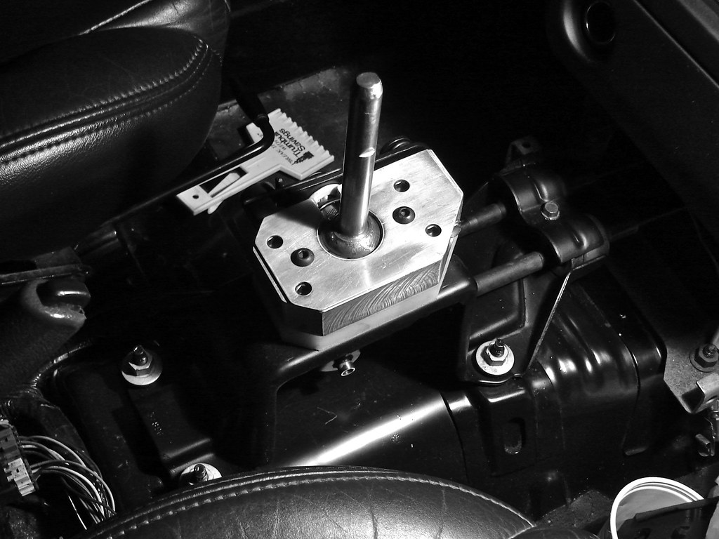
My first bit of progress was installation of the short-throw shifter and modified shifter cables. Removal of the existing cables from the car proved tricky. A few readings determined that the cables were to come out through the firewall from the interior. A firewall grommet that the shifter cables pass through retains them in place while a small plastic tab holds the grommet itself in place. To unseat this one needs to push the grommet toward the passenger side while pushing outward and it will supposedly pop out. This would be easy enough... if you could fit your hands in there. The spot your working in is wedged between the bottom of the dash and the exhaust tunnel. It took a few attempts, laying on my stomach on the drivers floor with a flashlight and an extra long screwdriver, but I got it. Once the grommet was popped I had to jack up the car so I get under there and guide the remaining length of cable out. Then, of course, the new ones went back in. Reseating the grommet was as easy as a few smacks with my palm. Dropping the shifter in was straight forward and the cables were attached with some stainless steel socket cap screws. Scuffing and painting the bracket that retains the cables at the front of the shifter was a last minute detail. First impressions? This thing feels unlike any shifter I've played with before. This is more like the Berg shifter in the '60 Beetle and less like the previous Saturn shifter I had built. It almost feels weighted with zero play in neutral and a very tight shift action.
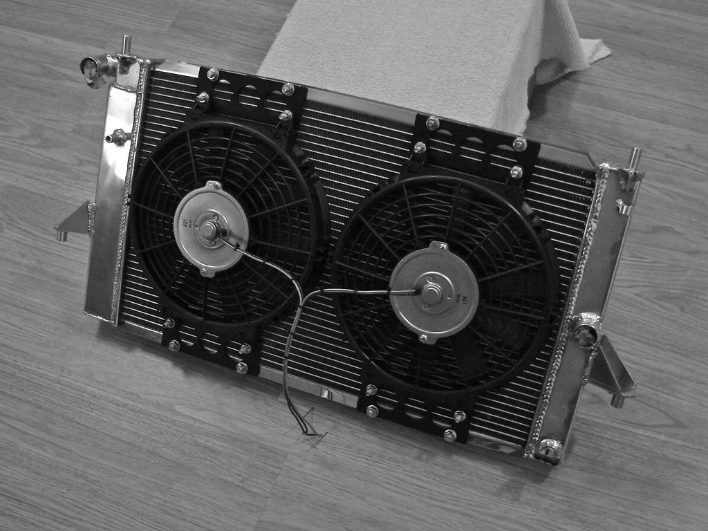
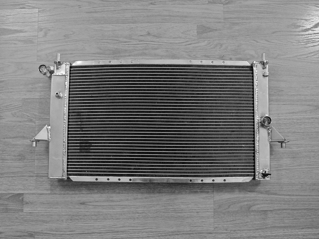
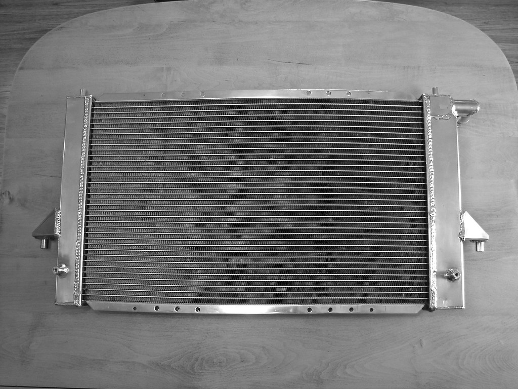
The AMR Engineering radiator is finally ready to go in. Like most things, after I opened the box, I found that I wasn't going to be able to leave it alone. The first thing I did was nix the mounting tabs that had been incorporated for mounting an OEM fan and shroud. This involved a cutoff wheel, some filing, a lot of sanding, then a buffing wheel. Shortly after producing the new shine I found myself torn over the finish and I heavily debated sending it out to be black anodized. For the time being I've sat on my hands, though I may still change things in the future.
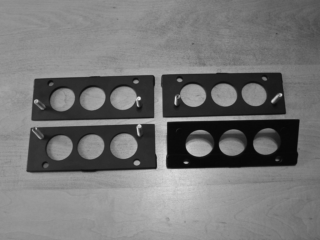
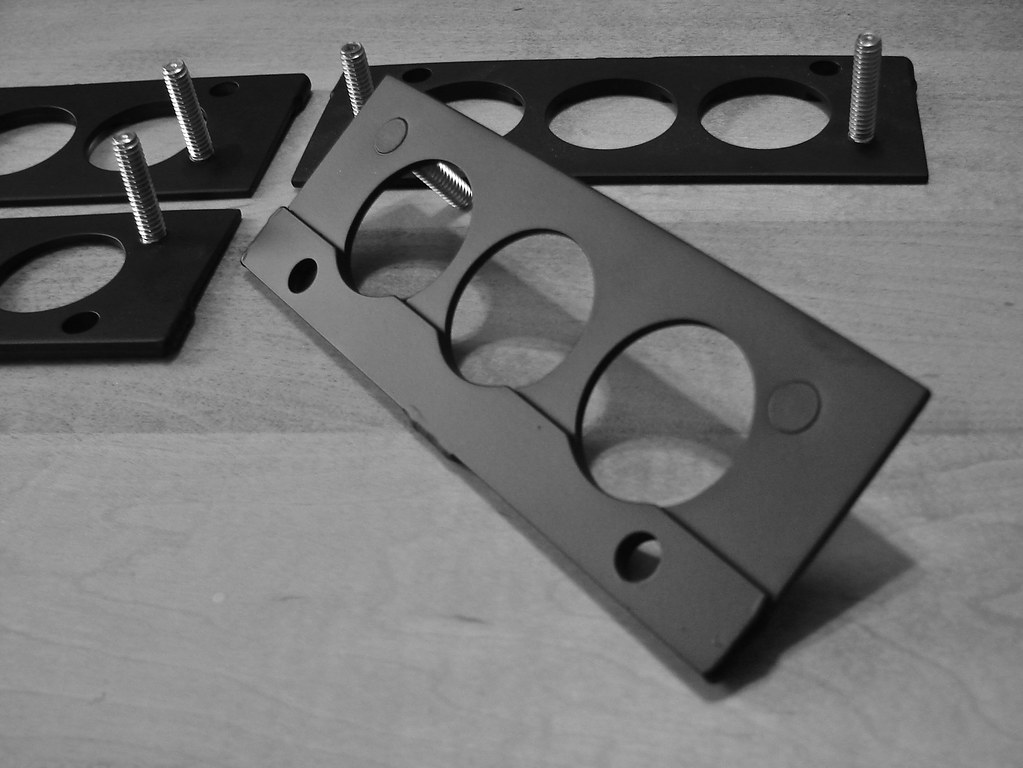
The fans I am running are a pair of 10" Proform slim fans. I have never been a fan of the zip-tie method of mounting so I decided to make a set of brackets to utilize the holes at the top and bottom of the core. These were fabricated out of some stacked 1/8" aluminum I had my Dad shear up at work. The bottom piece adds the thickness (or step) needed for the bracket to clear the radiator fins (and keep the fans from resting of the radiator core). After I trimmed these bottom pieces to size I drilled pilot holes to bolt them in position on the actual bracket.
After having them TIG welded into place (on the bottom and ends) I was able to remove the temporary hardware and drill the holes out to size. To maintain symmetry an additional hole was drilled at each grouping of holes. Next I laid out holes for the pem studs, that would secure the fans, by mounting my brackets to the radiator and mocking up the fans. Much to my frustration I discovered that the radiator has a bit of a crown to it, only after trying many times to make all of the holes parallel to each other. With some fussing I was able to make everything close, especially by drilling out the holes on the fan mounting tabs. From just a function aspect the brackets were done but they were rather plain looking so I laid out three large holes on each bracket and went to town with a hole saw (I guess I could lie and say it was for the weight savings). To finish I cleaned up all of the edges and dropped off to be powdercoated flat black. Outer mounting hardware are flared stainless steel nuts and bolts from McMaster Carr while the inner pem studs and flared nuts were provided by Dad. The only thing that has put off final installation has been fan wiring. I zip-tied the wiring all neatly and just need to scam an OEM fan plug and wiring to solder into place. Regrettably I pitched the stock fan and shroud that I had taken out.
My current work in progress has been something I've come to refer to as "THE hole". The hole came into existence as a mounting solution for my 8-circuit Hella fuse block (which will be the defense for the MS2 and gauges). Originally I wanted to mount it beneath the dash top near all of the new wiring but it was too large. Then I toyed with mounting it under the dash next to the interior fuse block but I didn't like it (this idea got as far as starting a mounting plate). After that I started looking at the glove box. It would be more accessible, than under the dash top, as well as a cleaner and more trick installation than if I put at the passenger's feet. Initially I tried to design something that would box in the MS2 while making a spot to mount the block right above it. After several approaches I couldn't find a way that wouldn't interfere with the compartment's latch.
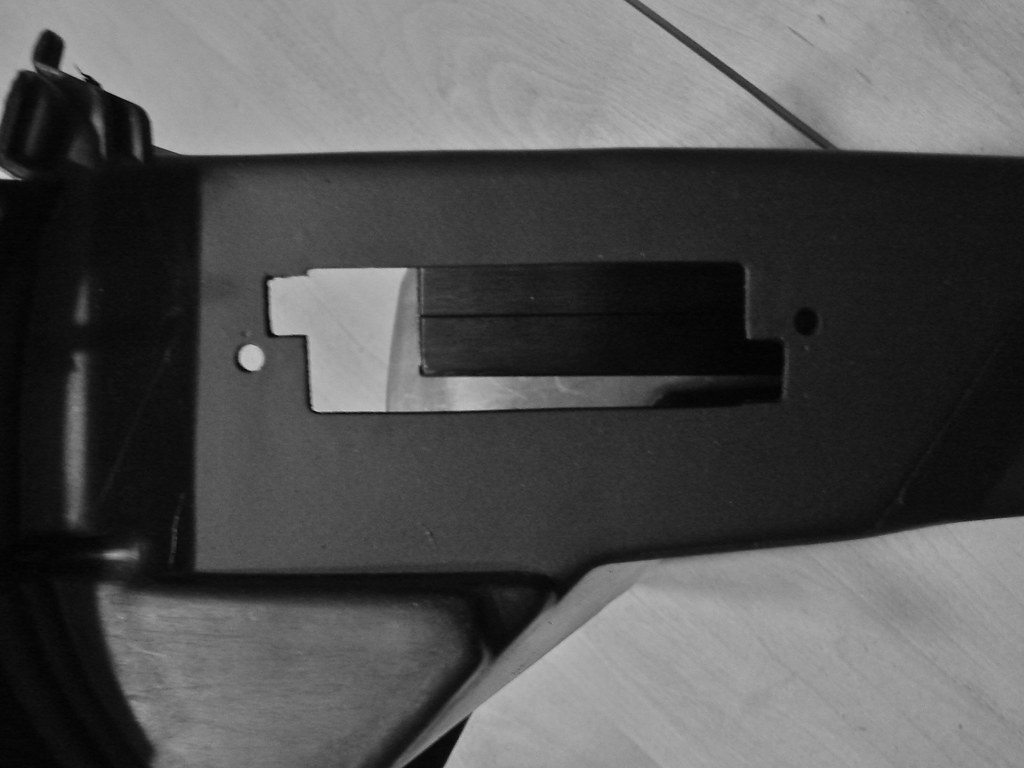
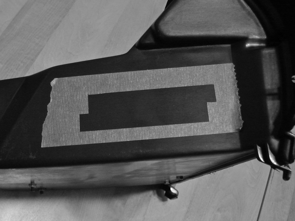
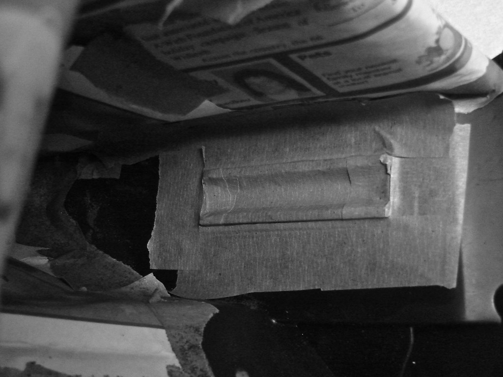
So I looked at mounting it on the driver's side of the glove box. I could have simply slapped it to the inner-side I wanted the installation to be far nicer. This is how the hole started. I would mount my additional fuse block flush from the backside to make it less intrusive and hide my wiring. After some measurements I made a template in cardboard to test fit the block in the hole. Eventually I transferred this onto a piece of painters tape which I then, after getting thing lined up, stuck on the outside of the glove box. The area to be cut out was traced with an exacto knife and removed so I had my outline. Normally I do these things with a dremel but, unfortunately, ours is dead so I made do with some drilling and the blade from a hacksaw. The final shape came from (a lot of) filing, working my way up the edges of the template.
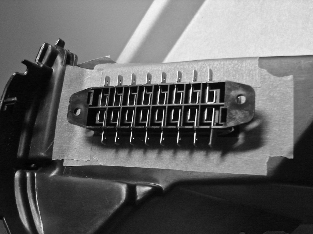
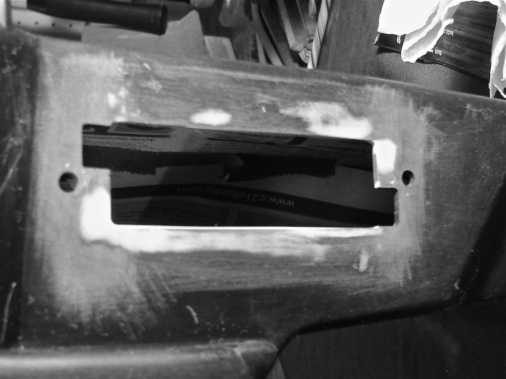
I periodically test fit the Hella fuse block until I got a beautiful hole. Then, when I went to layout the two mounting holes, I realized I had made a mistake! You'll see there are two slots on opposite corners of the hole. These are for the tabs on the fuse block cover to clip into the base and they were upside down. When I had transferred my pattern to tape I had forgotten to flip it so, theoretically, the fuse block would be mounted facing the wrong way. After a moment of face-to-palm I set about fixing my mistake while the overtime of hole making prompted an emphasis on "the" in "the hole". Anyway I shaped and epoxied some scrap plastic into place of the incorrect slots. After reshaping these corners of the hole I did some filler work (completely unnecessary but I don't like these things looking like hack jobs so I was going to go through the trouble). I also took the trouble to do some filling with the fuse box masked off and in place to tighten the hole. A few sessions of coating and sanding later I was able to remake the slots. Once I was satisfied with everything I did some masking and some prep to give the area a few coats of flat black Krylon Plastic Fusion (the same stuff I used on the radio bezel). And that brings us up to today! For the inner-side of the glove box I had planned on laying down some adhesive backed felt. The repairs have made it kind of necessary now.
No comments:
Post a Comment