November 30, 2010

First Fresh Post

We are up to speed! I can finally move onto posting updates with new progress. Please forgive the gap between my last archive post and now. I definitely have my work cut out for me after transferring my old posts, re-editing all of my photos, and switching to a better image host (Flickr). So what have I gotten done in the meantime? 


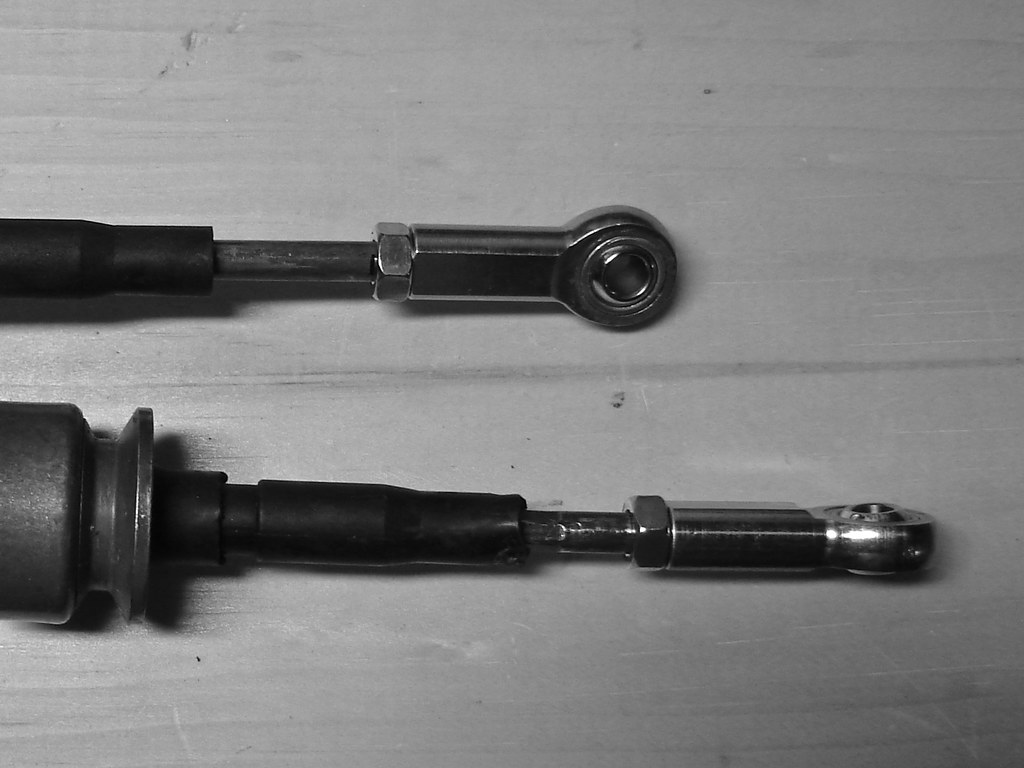
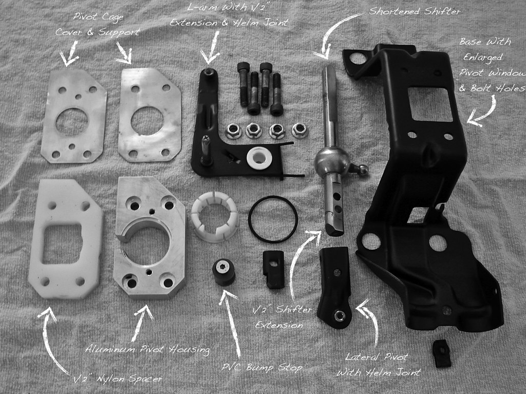
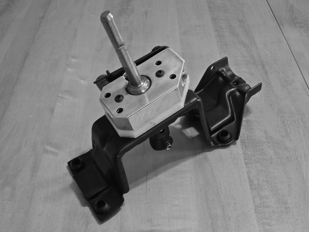
Yesterday, picking up on my shifter build, I altered the interior end of a spare set of shifter cables. One of the features of the new shifter was mounting for ball joint rod ends (or helm joints), from McMaster-Carr (part #6072K155), to eliminate the stock plastic cable ends. Attaching these was a very straight forward procedure. I eyeballed the rod ends against the stock ends so I could get a rough measurement of how far to thread the metal rod (marked with a sharpie).

October 06, 2010

Getting this blog up to speed...


Introduction

The name "Detail Junky" stems from my obsession with my car and all of the little things. The prior names for this build was "the high school budget build", a name that quickly went obsolete. The tallied investments have proved bank breaking but all of this progess wouldn't have been possible if I'd avoided pleading poverty every time I made a purchase. In retrospect I imagine I'd be a few steps behind if I'd been afraid to spend. When it came to spending I always shot (and shoot) for the best. When it came to working there was alot of cussing, an unhelpful Haynes manual, the forums, alot of common sense, and a very patient mentor (thanks to Dad). All of the headaches, the many stripped fastners, and other nightmares have contributed heavily to a never ending learning curve, something this car has been the absolute foundation of.


October 05, 2010

New home for "The Detail Junky" build...

Sixthsphere.com is going through some changes and I've decided to move my build to its own dedicated page. This will also give me a chance to reformat my build with easier access to information while providing better quality images (the quality of my current image host, photobucket, is awful).


August 18, 2010

Shifter Overkill (August 2010)...

This project was good practice for a few different machining procedures. The results weren't perfect but were pretty good for a novice (nor would they affect the performance of the shifter).

Shifter Build, August 18th, 2010: "I am a little overdue to add this to my build thread. Some of you probably already saw it in the thread I had in the 'Performance' section. Anyway I had previously built a nice short throw shifter for the SL2 in high school but the opportunity arose to build an ever better one. Dad had built a trick unit for the TDI but couldn't science out the reverse lock the Volkswagens have. At my disposal I had a shifter with a machined aluminum pivot housing (for the plastic cage) and lower pivot points with mounting for helm joints. The catch was the shifter was essentially backwards from a Saturn shifter. I scored up an unmolested shifter from Justin (d3ad1ysp0rk) and set aside everything I would need from the two shifters. On the stock base I enlarged the window to clear the movements of the main pivot, drilled out the four mounting holes for larger hardware, and made a notch for the helm joint on the L-arm to pass through. To make use of the L-arm the helm pivot from the TDI shifter was cut off and welded to the Saturn L-arm 1/2" lower than stock. The aluminum block had to be flipped over with the lip for the plastic cage re-machined (accomplished on my fathers lathe), the holes for the four bolts re-countersunk, and a hole for a "bumper" drilled and tap. The bumper was added to properly restrict vertical movement of the L-arm (like the tab on the stock plastic pivot housings). I made the bumper out of a piece of grey PVC, notched to clear the L-arm movements, and countersunk on one end for a flush fit of the mounting hardware. The other pivot point was extended by adding a 1/2" of material to the base of the shifter rod (TIG welded), re-machining the flats, and re-drilling the hole to mount the inner pivot; accomplished with a hex-head through-bolt with one side of the inner pivot threaded. The top of the shifter was cut down and the flats/notches for the shift knob were re-created with by hand with a mill file. The last piece I made was a plate to go over the top of the shifter base to help secure the plastic cage. Other pre-existing details include the 1/2" nylon spacer (to raise the main pivot) and a bronze bushing for the L-arm pivot (secured by a stainless steel nylon nut). The shifter still isn't in the car as I still need to purchase the helm joints to modify the shifter cables. Lately I've been plowing through the wiring to the gauge cluster, which is almost done, so hopefully I'll have another update soon."

June 08, 2010

Gauge Overkill (June-September 2010)...

This is a project that I am particularly proud of. At the time of the original posting I was still working out my wiring which I eventually wrapped up in August/September (these posts have been included at the bottom).

Gauge Cluster Build, June 8th, 2010: "I dreamed up this set-up awhile ago and it evolved a little bit throughout the building process. It initially started with the 3G head unit which I purchased years ago (since the SL2 is down to the two front speakers audio isn't a big deal in this car). I knew I wanted to make it appear OEM in fitment and that to do so I was going to have to alter the trim bezel. Fast forward to the past couple of months; I had toyed around with lots of different mounting solutions for the gauges but ultimately decided I wanted to consolidate them right in front of me. To have the room to put all of the gauges in one place I would have to mount the radio as low as possible. This was accomplished by resting the unit in the cradle of the original 94' radio with some shims to get the unit where I wanted it, then altering the 3G brackets to tie into the mounting points at the top of the climate control. There is a slight curvature to the bottom edge of the radio face on the 3G unit so I have it sitting in a way that it pretty much sits on the bridge right below it. I had debated trying to recreate this curve on the actual bezel but found it much simpler to do it the way described. Fortunately the upper edge of the radio face was straight. I also filled in the holes at the top of the bezel where the adjustment wheels for the vents used to be.
 
After the unit mounting was settled I moved onto the altering the bezel. I had been sitting on a few of these bezels with one that was mint (really just no broken clips) and two others for material. After some measurements I cut up the spare bezel for the bridge that runs across the top of the radio and did some trimming to the good bezel so I could graft it in. Everything was mated together with plastic epoxy as well as reinforced over the joints on the backside to ensure things were secure. Once all was said and done I was able to cut out all of the unused bridging to make room for the gauges. Of course there was a ton of finish work involved. I spent a lot of time knocking down the plastic materials textured finish with 400 grit and used a few coats of Kyrlon Plastic Fusion to fill any blemishs with a sanding and final coat.
 
The plate the gauges are mounted in is just a sheet of aluminum (1/8" I think) my Dad sheered up for me. This started out as a cardboard template after finishing up the area around the radio. It should have been pretty straight forward but the way the bezel is shaped made nothing square. I was actually quite paranoid that I had take incorrect measurements while doing the graft but after triple-checking everything I determined it was just the way the bezel is. So while laying out everything I had to make adjustments to maintain the illusion that nothing was crooked. Once done with cardboard I duplicated it in aluminum. I trimmed the edges first, then duplicated the slight curvature of the bezel by bending it over an old fire extinguisher. I cut the holes afterward to compensate for any distortion from the bending (which honestly wasn't all that much).
 
At first I was going to just have it powdercoated in a textured black finish but changed my mind while flipping through some street rodding books. I had seen a dash that was wrapped in vinyl with the button head hardware and though it had a touch of class while appearing purely functional so I adapted what I saw. The vinyl also gave the gauges a little extra something to seat into as the aren't on an entirely flat service. The material also dimpled around the hardware which gives the whole thing a little extra depth. The vinyl wrapped panel is secured to the panel by the visible hardware all the way around. I am still on fence as to whether the stuff I used to big but it was the smallest I could find locally. I also backed the existed mounting points (dash-to-bezel clips) with some velcro. I have to go back and make some adjustments to the radio as there is a small gap at the bottom of the face..."
Gauge Cluster Wiring, August 16th, 2010: "I've finally gotten somewhere with the wiring for my Autometer gauge cluster. To be honest I didn't have a clue as to how to tackle wiring for six gauges other than knowing I want a clean execution. What you see grew out of a single starting point and I am pretty pleased with the outcome. When I started I knew that I didn't want the gauges to be "hard wired" into the car in the even that I need to remove the cluster for servicing. With this in mind I began by pinning out any wiring that didn't come as a plug in affair. This included all of the wiring for illumination and the power/ground wires fixed in the back of the Pyrometer now all in a 12-pin plug. The connections for power, ground, and sending units on the back of the oil pressure and temperature gauges had spades for press-on terminals so I dug out some color coordinated wires (red for power, black for ground, purple for pressure, blue for temperature) and soldered press on terminals on the gauge end and pins for a 6-pin plug on the other. When I was done with the female plug ends I started the harness for the male halves of the 6-pin and 12-pin plugs. To keep things simple I made jumpers from single leads to plug into the appropriate pins (you can best see this with the white illumination/black ground wiring in the bottom plug in the first picture). The WBO2 and fuel pressure gauges came with their own plugs (the two small black ones, first picture) and with my own plugs done I plugged everything into the back of the cluster to merge with zip-ties. From the overall harness I separated all of my power wires which will go to their own fuse strip (which I still need to purchase). To ground everything I found a nice two wire bolt-on spade that I tied into each of my own plugs (seen going off the top of the first picture). The rest of the wiring will go through the firewall to the engine bays where everything will be connected to their senders/sensors and so on."
 
Gauge Cluster Updates, September 27th, 2010: "Been busy wrapping up some of the previously posted projects and starting others. I received an antenna adapter for the 3G head unit earlier in the week. The lack-of had been holding me up from doing the final install of the altered bezel/gauge cluster as I didn't want to keep taking things apart. Since I had to pull the radio I double checked my adapter harness and wrapped it in some plastic loom for the final install. I also took the chance for some pictures of my radio brackets and adapter harness.
 
Plugging in all my gauges was a little tricky with everything being a bit bulky but went together well otherwise. Sometime in the future I will have to take things apart to create additional mounting points for the bezel. As mentioned in an earlier post the weight of the six gauges is working against the factory clips. In addition the wiring is also pushing outward on the back of the gauges. I had aided the install with some velcro but the whole thing isn't as secure as I'd like. Wiring for the pyrometer and the hose for the boost gauge have been added to the growing sub-harness that goes through the grommet in the firewall. I spent some time zip-tying that on the interior side. Aside from a wire for a future manual fan switch I should be done shoving a coat hangar through there."

April 12, 2010

Megasquirt Wiring Schematic (April 2010)...

My old posts are getting more detailed and closer so they will be posted individually. This one includes the MS2 schematic I made when it came time to wiring the unit up. 


MS2 Wiring, April 12th, 2010: "Wiring is a new game for me so I was pretty anxious about wiring up the MS2. I took my time getting comfortable with both the Saturn and Megasquirt schematics before making any cuts (below is a schematic I created). Then I spent some more time sorting out my approach to the wiring. I wanted the outcome to be tidy. Starting with a DIYAutoTune pre-made harness I first separated any wiring destined for the engine bay (in this case the MS2 ground, secondary CTS, and secondary IAT) and pulled them through the firewall grommet attached to the PCM/hood latch cable. Under the dash I separated wiring into direct or splice connections. Before doing any trimming of the DIYAutoTune harness I created a predetermined amount of slack between where I would be soldering and where the harness was connected to the MS2 (in the glovebox). This would give me the slack needed in the event that I ever need to remove/unplug the MS2 from the glovebox and so I could tuck my under dash wiring by reeling in the MS2 harness. Then I did my trimming, leaving a little extra length in the brown wire (Pin 36) for a future Ford EDIS. I had considered de-pinning all of the unused features (IAC, FIdle, etc.) but opted to just cut the wiring a little shorter to hide in the loom. Today I soldered, shrink wrapped, and zip-tied all of my connections with the exception of the wiring that is in the engine bay and got everything tucked up nicely. In other news I also finally installed my SDA dog bones. I originally purchased these unassembled so I could have them color matched to my other black parts. I was disappointed by the sleeves provided for the bushings so I had a friend of mine machine some new ones out of stainless steel."

Saturn to MS2 Schematic

Function : Pin# (PCM/MS2) : Wire Color (PCM) : Wire Color (MS2) : Connection Type
Power        ... A7/28             ... Pink/Black          ... Red                  ... Splice
TPS Input   ... A8/22             ... Dark Blue            ... Blue                  ... Direct
Pin 36        ... C11/36           ... White                  ... Brown               ... Splice (For future reference)
O2 Sensor   ... D9/23            ... White/Black        ... Pink                  ... Direct
Ignition      ... D12/24           ... Purple/White      ... White               ... Splice (Tach Signal)

Injector 4 ... D13/35 ... Light Blue      ... Blue ... Direct
Injector 3 ... D14/34 ... Light Blue      ... Blue ... Direct
Injector 2 ... D15/33 ... Light Green ... Green ... Direct
Injector 1 ... D16/32 ... Light Green ... Green ... Direct

IAT Input ... 20 ... Direct (Secondary Sensor)
CTS Feed ... 21 ... Direct (Secondary Sensor)
Fuel Pump ... 37 ... Bypass MS2, PCM will power

*Splice Connection: Wiring is routed to both the PCM/MS2
*Direct Connection: Wiring bypasses the PCM (goes only to MS2)